The Hardest Part of a 3D Kinetic LED Screen May Have Little to Do with the “Screen” Itself
One-Sentence Definition: A 3D Kinetic LED Screen is not simply “an LED screen that moves.” It is an integrated electromechanical engineering system in which four subsystems—mechanical structure, motion control, power system, and signal system—are deeply coupled. A weakness in any one of these subsystems can turn a screen from “able to move” into “unable to move well.”
1. Take Apart a 3D Kinetic LED Screen, and You’ll Find Much More Than LEDs
For most people, an LED screen is simply “a panel that displays images.”
Take apart a standard LED display, and you will typically find LED modules, cabinets, power supplies, receiving cards, and cables.
But take apart a 3D Kinetic LED Screen, and you will find something very different.
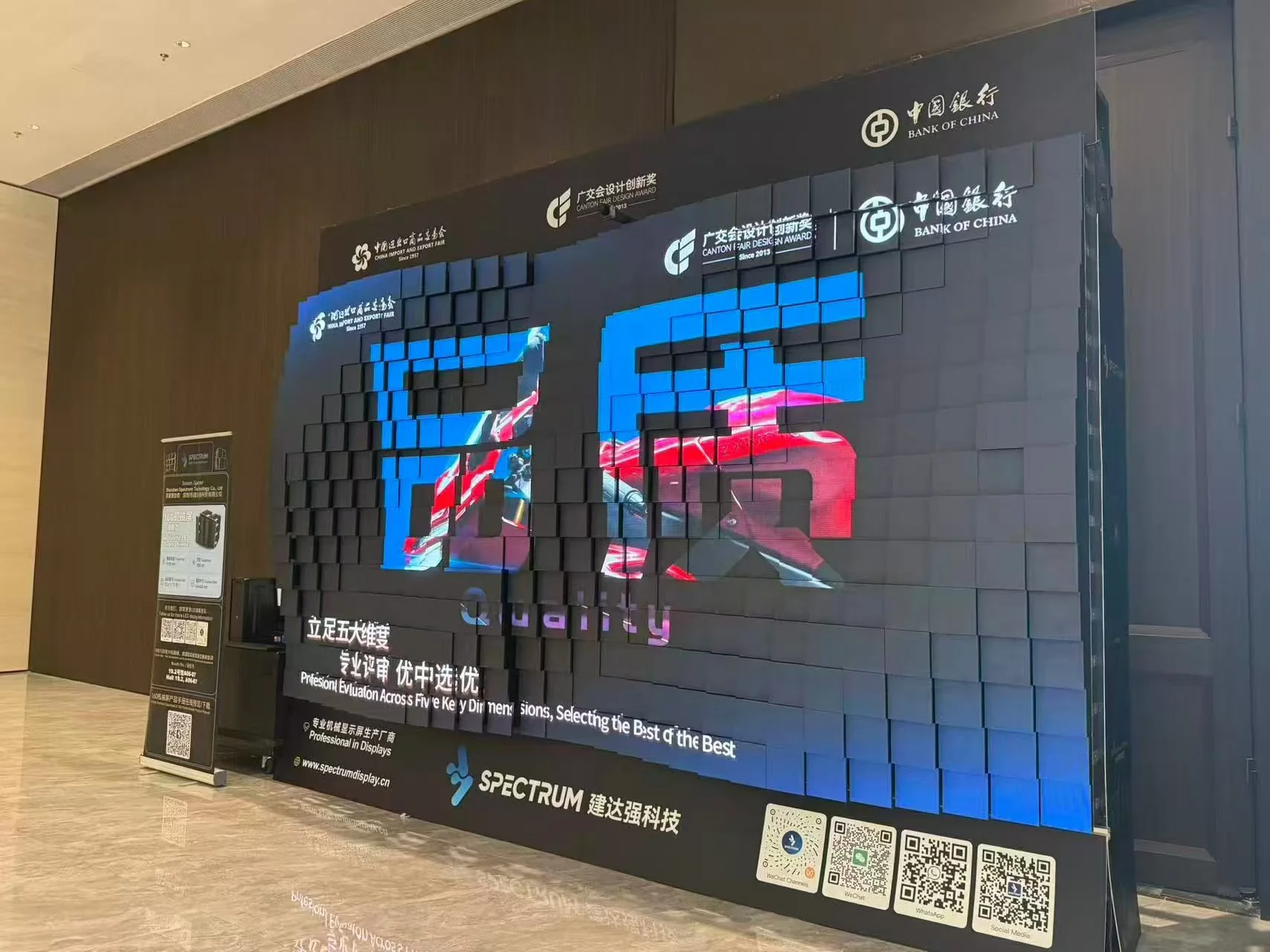
In addition to LED modules and cabinets, there are servo motors, industrial-grade linear guide rails, transmission mechanisms, multi-axis motion controllers, motor drives, position sensors, and distributed control networks.
Behind every LED module is an independent electromechanical motion system supporting its physical movement.
In other words, a 3D Kinetic LED Screen is not fundamentally just a “screen.”
It is an integrated electromechanical system.
This system consists of four deeply interconnected subsystems:
mechanical structure, motion control, power system, and signal system.
A design weakness in any one of them will eventually reveal itself during operation—whether as reduced motion accuracy, synchronization delays, increased noise, or frequent maintenance requirements.
Below, we break down the engineering logic behind each of these four subsystems.
2. Subsystem 1: Mechanical Structure — The Skeleton of Motion
The mechanical structure is the “skeleton” of a 3D Kinetic LED Screen.
It determines whether the screen can move, whether it moves steadily, and whether the physical movement feels precise and refined.
Core Components
LED Modules and Motion Units
Each motion unit consists of an LED module and an independent mechanical motion mechanism.
Taking the product portfolio of Shenzhen Spectrum Technology Co., Ltd. (Spectrum Display) as an example:
- SPKI-166: 165.6 × 165.6 mm modules, 36 motion units/m²
- SPKI-160: 160 × 160 mm modules, 38.6 motion units/m²
- SPKI-250: 248.5 × 248.5 mm large-format motion units, only 16 motion units/m²
- SPKO-250 outdoor model: 248 × 248 mm modules, 16 motion units/m²
Industrial-Grade Linear Guide Rails
The linear guide rail is the “track” of each motion unit.
Its precision directly affects displacement accuracy and long-term operating stability.
Spectrum Display uses industrial-grade linear guide rails combined with precision manufacturing processes, with more than 90% of components precision-machined, helping ensure accurate positioning throughout repeated extension and retraction cycles.
Die-Cast Aluminum Cabinets
The cabinet serves as the structural frame supporting the motion units.
Spectrum Display uses die-cast aluminum cabinets across the product range to balance structural strength with reduced weight.
The SPKI-250 cabinet weighs only 13 kg, the SPKI-166 cabinet weighs 18 kg, while the SPKI-160 weighs 75 kg/m².
For the outdoor SPKO-250, each cabinet weighs 17 kg, equivalent to approximately 68 kg/m².
Key Engineering Specifications
| Metric | What It Means | Spectrum Display Standard |
|---|---|---|
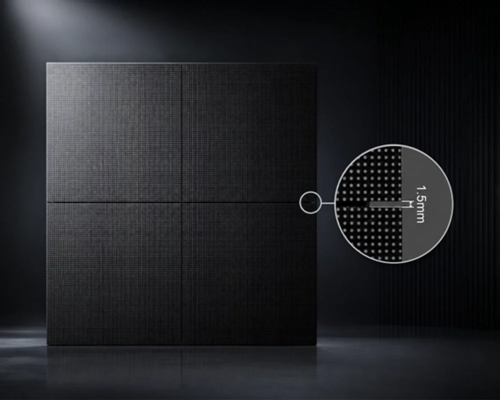
| Physical Module Gap | Physical spacing between motion units | SPKI-166: 1.0 mm; SPKI-160: 1.0 mm; SPKI-250: 1.5 mm; SPKO-250: 2.0 mm |
| Visual Seam | Perceived seam after LED pixel-offset optimization | SPKI-166: 0.2 mm; SPKI-160: 0.8 mm; SPKI-250: 0.9 mm; SPKO-250: 2.0 mm |
| Motion Travel | Maximum forward/backward displacement of each motion unit | SPKI-166: 230 mm; SPKI-160: 200 mm; SPKI-250: 200 mm; SPKO-250: 200 mm; SPKO-500: 600 mm |
| System Depth | Display body depth in standby mode | SPKI-166: 350 mm; SPKI-160: 330 mm; SPKI-250: 330 mm; SPKO-250: 330 mm, plus maintenance access |
The quality of the mechanical structure determines the difference between a screen that can move and one that moves with precision and refinement.
3. Subsystem 2: Motion Control — The Nervous System of Motion
The motion control system is the “nervous system” of a 3D Kinetic LED Screen.
Its job is to translate digital content instructions into precise physical movement.
Core Components
Servo Motors and Drives
Traditional mechanical displays often use open-loop stepper motors—the system sends a command but does not verify whether the motor has actually reached the required position.
Spectrum Display moves away from conventional stepper-based solutions and uses a proprietary bus-based servo motor system as the core motion architecture.
Each servo motor is equipped with a high-precision magnetic encoder that provides real-time position feedback.
Multi-Axis Motion Controller
A large 3D Kinetic LED Screen may contain hundreds or even thousands of independent motion units.
Coordinating them requires a multi-axis motion control architecture.
Spectrum Display’s control system supports up to 65,536 motion units online simultaneously, with each individual channel supporting peer-to-peer communication with up to 48 motion units.
Closed-Loop Control Algorithm
Combined with a 32-bit MCU and high-precision magnetic encoder, the system enables absolute position control.
A Field-Oriented Control (FOC) algorithm helps ensure smooth, quiet, and efficient motor operation.
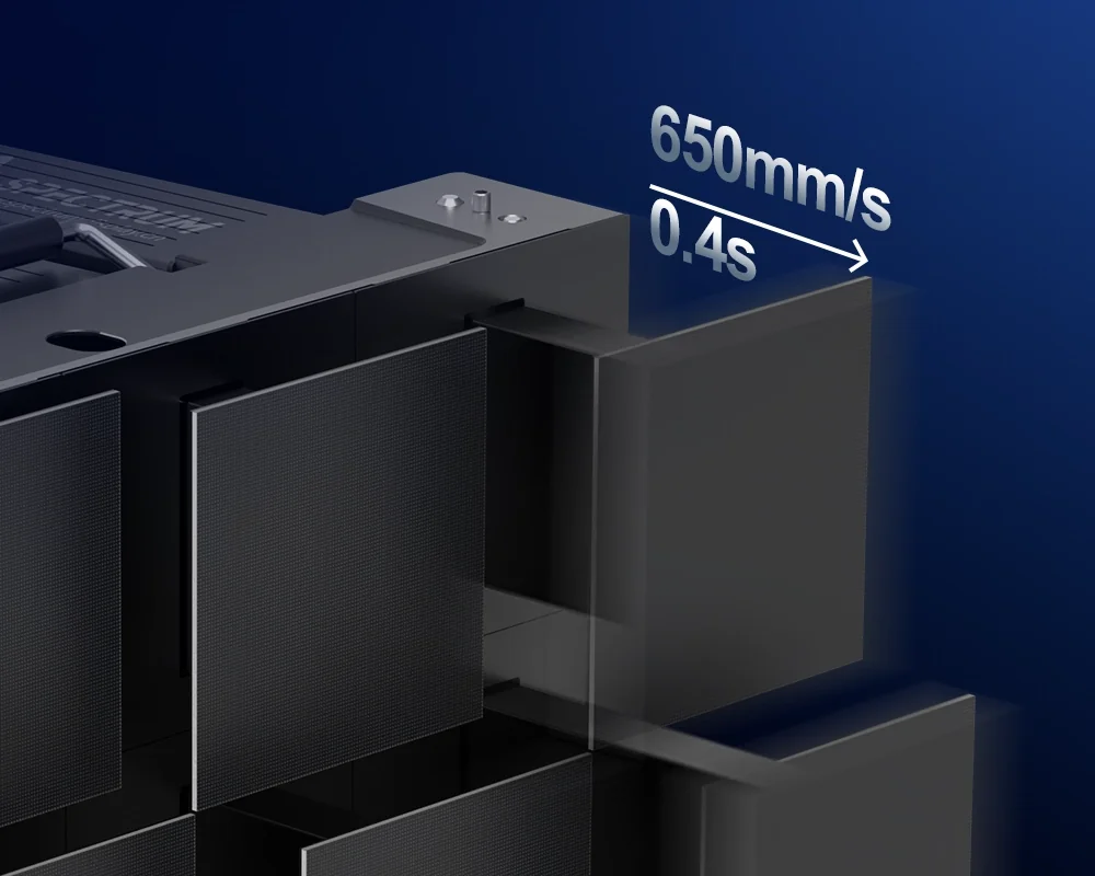
Indoor models achieve a full-stroke motion time of less than 0.5 seconds, while the SPKI-166 reaches 0.4 seconds.
Key Engineering Specifications
| Metric | What It Means | Spectrum Display Standard |
|---|---|---|
| Control Method | Open-loop stepper vs. closed-loop servo | Closed-loop servo control |
| Maximum Control Capacity | Maximum number of motion units controlled by one system | 65,536 units |
| Full-Stroke Time | Time from fully retracted to fully extended | SPKI-166: 0.4 s; SPKI-160: 0.4 s; SPKI-250: 0.5 s; SPKO-250: 0.5 s |
| Protocol Compatibility | Supported industrial control protocols | DMX512, Art-Net, sACN |
| Anti-Pinch Protection | Safety response when resistance is detected | Triggered at 3 kg; motor immediately disabled and power cut |
The motion control system determines the difference between a screen that merely moves and one that moves precisely, consistently, and safely.
4. Subsystem 3: Power System — The Lifeblood of Motion
The power system is the “lifeblood” of a 3D Kinetic LED Screen.
It must supply power not only to the LED display itself, but also to the servo motors, drives, control system, and sensors.
Core Components
Power Distribution Design
The power requirements of a large mechanical LED installation can be significantly higher than those of a conventional LED screen.
Taking Spectrum Display’s product range as an example:
- SPKI-166: 920 W/m²
- SPKI-160: 965 W/m²
- SPKI-250: 720 W/m²
- SPKO-250 outdoor model: 1320 W/m²
For a 100 m² mechanical LED wall, the peak power requirement of the display system alone can exceed 100 kW.
Zoned Power Distribution
For large projects, Spectrum Display uses an intelligent zoned power distribution architecture.
Power can be drawn from distribution points on each floor, helping minimize voltage drop over long cable runs while simplifying maintenance.
At the Mandarin Oriental Jakarta project, each floor was equipped with an independent 55 kW distribution box, with multifunction cards used for intelligent switching and power control.
Power Redundancy
For mission-critical projects, power redundancy mechanisms can be incorporated so that the system can continue operating if a single power circuit fails.
Key Engineering Specifications
| Metric | What It Means | Spectrum Display Standard |
|---|---|---|
| Power per Square Meter | Peak power requirement per unit area | SPKI-166: 920 W/m²; SPKI-160: 965 W/m²; SPKI-250: 720 W/m²; SPKO-250: 1320 W/m² |
| Power Supply Requirement | Electrical standard based on total power | ≤3 kW: 220 V single-phase; ≥3 kW: 380 V three-phase/five-wire |
| Voltage Drop Control | Power loss over long-distance distribution | Zoned power distribution design |
| Cooling Method | Thermal management for power and drive systems | Indoor: open self-cooling with auxiliary fans; Outdoor: semi-enclosed self-cooling with auxiliary fans |
The quality of the power system determines the difference between a screen that can simply turn on and one that can operate reliably over the long term.
5. Subsystem 4: Signal System — The Language of Motion
The signal system is the “language” of a 3D Kinetic LED Screen.
It is responsible for transmitting video content and motion commands accurately to every display unit and motion unit.
Core Components
Display Signal
This handles the transmission of visual content.
For large-scale projects, the control architecture may need to move beyond DMX512 toward Ethernet-based protocols such as Art-Net and sACN, supporting larger numbers of control channels and longer transmission distances.
Motion Control Signal
This carries the displacement commands that drive each individual motion unit.
Spectrum Display uses a proprietary industrial-grade distributed control architecture with interference resistance and error-correction capabilities.
Every motion unit has a unique ID, allowing the system to automatically identify and establish the network when powered on.
Signal Redundancy
At the Mandarin Oriental Jakarta project, Spectrum Display equipped every control zone with two receiving cards—one primary and one backup.
If the primary signal cable fails unexpectedly, the backup system can take over immediately and seamlessly.
Key Engineering Specifications
| Metric | What It Means | Spectrum Display Standard |
|---|---|---|
| Display / Control Protocols | Protocols used for signal and control transmission | DMX512 / Art-Net / sACN |
| Control Architecture | Communication architecture for motion control | Proprietary industrial-grade distributed control |
| Signal Redundancy | Primary/backup signal switching mechanism | Dual redundancy with primary and backup receiving cards |
| Synchronization Accuracy | Synchronization between display content and physical motion | Millisecond-level synchronization |
The signal system determines the difference between a screen that can simply display content and one in which content and physical movement remain precisely synchronized and stable over time.
6. How the Four Subsystems Work Together: The Engineering Logic Behind a Real Project
The Singapore bar ceiling project provides a clear example of how these four subsystems work together.
Mechanical Structure
The SPKI-160’s 330 mm ultra-slim body and front-maintenance architecture allowed the screen to fit tightly within the limited ceiling cavity.
The 1440 × 3840 mm installation consists of approximately 88 independent motion units.
Motion Control
Through DMX512 integration with the bar’s lighting control system, the rhythm, travel, and frequency of the screen’s physical movement can synchronize with the DJ’s music at millisecond-level precision.
Power System
The power architecture provides stable power to both the LED display and servo motors, while the thermal management design supports long-term operation.
Signal System
Music and control signals are translated into physical movement commands, creating an effect in which the rhythm of the music becomes the rhythm of the screen.
All four subsystems are essential.
Mechanical structure determines whether the system can be installed.
Motion control determines how well it moves.
The power system determines whether it can operate reliably.
The signal system determines whether everything can remain precisely synchronized.
▶Video · YouTubeWhere Creative Vision Meets Engineering ExcellenceWatch on YouTube →
7. Conclusion
The hardest part of a 3D Kinetic LED Screen may have very little to do with the “screen” itself.
Key Takeaways
- Mechanical Structure — The Skeleton of Motion: Determines whether the screen can move and whether it can move smoothly and reliably.
- Motion Control — The Nervous System of Motion: Determines motion accuracy, synchronization, stability, and safety.
- Power System — The Lifeblood of Motion: Determines whether the entire system can operate reliably over the long term.
- Signal System — The Language of Motion: Determines whether visual content and physical movement can remain precisely synchronized.
Four-Subsystem Engineering Checklist
| Subsystem | Core Components | Key Engineering Metrics |
|---|---|---|
| Mechanical Structure | LED modules, linear guide rails, die-cast aluminum cabinets | Module gap ≤2.0 mm; design life >50,000 hours |
| Motion Control | Servo motors, multi-axis controllers, closed-loop algorithms | Up to 65,536 motion units; full-stroke time <0.5 s |
| Power System | Zoned power distribution, multifunction cards, power redundancy | 720–1320 W/m²; zoned power distribution |
| Signal System | Control protocols, distributed control, signal redundancy | DMX512 / Art-Net / sACN; dual primary/backup redundancy |
Recommendations for Buyers and Project Owners
- When evaluating a 3D Kinetic LED Screen, do not focus only on LED specifications. Ask for the engineering specifications of all four subsystems.
- Ask suppliers to provide information on mechanical design life, motion-control capacity, power distribution architecture, and signal redundancy.
- Whenever possible, visit the manufacturing facility in person. The quality of mechanical design and manufacturing processes becomes much easier to evaluate on the factory floor.
- For more technical information or a customized engineering solution, contact the Spectrum Display team through the Spectrum Display official website.