How Much Installation Depth Does an Outdoor Kinetic Screen Need? SPKO-250 Installation and Maintenance Space Explained
One-Sentence Definition: The installation depth of an outdoor kinetic screen is not a single fixed number. It is determined by three separate spatial requirements: static cabinet depth (330mm), dynamic motion stroke (200mm), and maintenance clearance depending on front- or rear-service access. When preparing architectural drawings, architects and system integrators must clearly distinguish between equipment depth and maintenance clearance.
1. The Architect’s Question: How Much Space Should Be Reserved?
During the design stage of an outdoor kinetic screen project, one of the most common questions from architects and façade consultants is:
“How deep is the screen? I only have 300mm behind the façade. Is that enough?”
The system integrator may answer:
“The cabinet depth is 330mm, but it depends on how you install it.”
This is a typical engineering communication gap.
For a conventional outdoor LED display, depth is primarily a static physical dimension.
For an Outdoor Kinetic Screen, however, “depth” consists of three completely different spatial requirements:
the static equipment depth, the forward motion stroke, and the rear or front maintenance clearance.
If only one of these dimensions is considered during architectural design, the drawings may look perfect—but the equipment may not fit or operate properly once it arrives on site.

2. Breaking Down “Depth”: Static Depth vs. Motion Stroke vs. Maintenance Clearance
To reserve the correct amount of space in architectural drawings, “depth” needs to be separated into three calculations.
1. Static Cabinet Depth
This is the physical depth of the equipment when all motion units are fully retracted, measured from the installation reference plane to the LED display surface.
2. Dynamic Motion Stroke
This is the maximum distance that the kinetic modules extend forward during operation.
3. Maintenance Clearance
This is the working space required for technicians to inspect, remove, repair, or replace motors, power supplies, control boards, and other internal components from either the front or rear of the display.
The distinction is critical:
Static cabinet depth + maintenance clearance determines the architectural space required behind or around the equipment.
Dynamic motion stroke determines the safety clearance that must remain unobstructed in front of the display.
These dimensions should never be treated as the same thing.
3. The Key Number: What Does the SPKO-250’s 330mm Cabinet Depth Actually Mean?
The SPKO-250 has a static cabinet depth of 330mm.
For an outdoor kinetic screen system, this compact depth provides significant advantages for architectural integration.
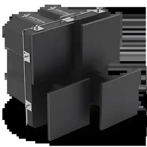
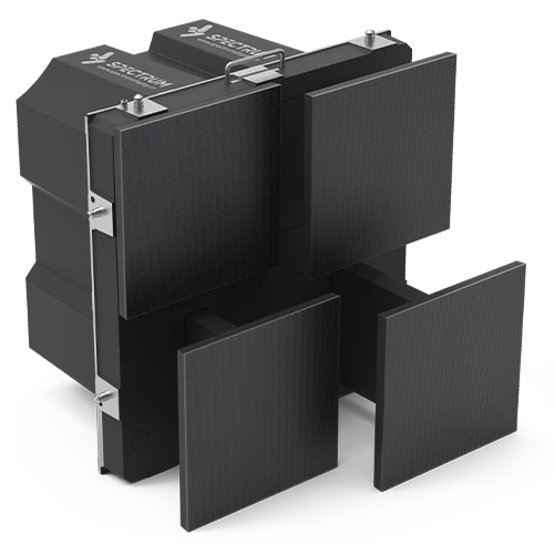
The SPKO-250 uses an integrated die-cast aluminum cabinet measuring 500 × 500mm and weighing approximately 17kg, with the cabinet depth controlled at 330mm.
This helps reduce the amount of architectural space required compared with larger conventional outdoor display structures combined with supporting steelwork.
However, one point is particularly important:
330mm refers only to the static depth of the screen cabinet itself.
It does not automatically represent the complete architectural depth required for the finished installation.
Additional space may still be required for power components, control boxes, cabling, structural connections, and maintenance access.
The SPKO-250 also provides a maximum physical motion stroke of 200mm.
This means that during operation, the LED surface can physically extend up to 200mm forward from its retracted position.
Therefore, the space in front of the display must also be treated as an active motion zone.
4. Space Requirements for Four Installation Methods
The SPKO-250 supports multiple installation configurations.
Each configuration creates different requirements for equipment depth, structural space, motion clearance, and maintenance access.
1. Wall-Mounted Installation
Equipment Depth: Reserve at least the required space for the 330mm cabinet depth between the architectural mounting plane and the display structure.
Front Clearance: The area in front of the display must provide at least 200mm of unobstructed motion clearance.
Glass curtain walls, protective railings, decorative panels, signage, or other architectural elements must not be positioned directly within this motion zone, otherwise the extending modules could collide with them.
Maintenance Method: Front maintenance is recommended when rear access is unavailable.
If the building façade does not allow technicians to enter from behind the display, modules and internal components can be serviced from the front without requiring a dedicated rear maintenance corridor.
2. Hoisted / Elevated Fixed Installation
Installation Depth: In addition to the 330mm screen body, sufficient space should be reserved for the load-bearing truss, suspension rods, structural connections, and cable routing.
Depending on the project structure, an additional 200–300mm may be required for these supporting systems.
Maintenance Method: Rear maintenance is strongly recommended.
For elevated installations, relying entirely on front access may require aerial work platforms or other work-at-height equipment every time maintenance is needed.
Where conditions allow, a rear maintenance corridor of at least 600mm should be considered so technicians can safely access the system.
3. Ground-Stacked Installation
Installation Depth: A ground-stacked system requires a supporting base.
Additional rear bracing or a floor-mounted steel structure may also be necessary to resist wind loads.
As a result, the total structural depth can exceed 500mm, depending on the engineering design.
Maintenance Method: Rear maintenance is generally preferred.
Where possible, an approximately 800mm-wide maintenance passage behind the display gives technicians sufficient room to inspect and service the system directly from ground level.
4. Face-Up Installation
Installation Depth: Face-up installations are typically integrated into floors, atriums, landscape structures, or installations above water features.
A recessed structural space may be required below the finished surface to accommodate the screen body, supporting structure, cabling, and drainage system.
Maintenance Method: A combination of front and rear/side maintenance access may be required.
Because the finished floor surface should not need to be repeatedly dismantled, the architectural design should incorporate concealed access openings, maintenance pits, or side-access corridors from the beginning.
5. Practical Checklist for Architects: What Else Should Be Confirmed Besides Depth?
Reserving sufficient depth is only one part of architectural integration.
During the design stage, system integrators, architects, façade consultants, and structural engineers should also confirm four critical requirements.
1. Load Bearing
The SPKO-250 weighs approximately 68kg/m² at the equipment level.
However, this is not the complete structural design load.
Once the supporting steel structure, dynamic mechanical loads, and wind loads are considered—particularly in typhoon-prone regions—the building anchoring system and embedded structural connections must be recalculated accordingly.
2. Cooling and Ventilation
Although the static cabinet depth is only 330mm, sufficient airflow must still be maintained around the equipment.
If the entire system is installed inside a completely enclosed cavity with poor ventilation, internally generated heat may accumulate and affect motors, electronics, and long-term system stability.
3. Drainage
For building façades exposed to rain, water must not be allowed to accumulate around the bottom of the cabinets or flow uncontrollably into the rear installation cavity.
Appropriate drip edges, drainage channels, and water-management paths should be incorporated into the architectural design.
4. Power and Signal Conduits
Additional space should be reserved for cable routing and conduits.
Depending on the project configuration, approximately 50–100mm of routing space may be required for main power connections, fiber-optic cables, network cables, and associated wiring.
For larger installations, the electrical design may use 380V three-phase power, subject to the final system power requirements and local electrical standards.
▶Video · YouTubeFrom Installation to Motion — onsite installation and commissioningWatch on YouTube →
6. Frequently Asked Questions (FAQ)
Q1: Can I fully recess the screen into a wall and expose only the LED surface without leaving any rear maintenance space?
A: Yes, but the project must use a front-maintenance configuration.
If there is no rear maintenance corridor, technicians need sufficient working access in front of the display so that modules and internal components can be removed and serviced from the front.
This approach is particularly useful when the kinetic screen needs to be integrated closely into an architectural façade.
Q2: There is only 220mm of space in front of the screen. Is that enough for a 200mm motion stroke?
A: It is not recommended.
Although there is theoretically 20mm of additional space, real projects must account for installation tolerances, structural movement, wind-induced displacement, and other engineering deviations.
For a system with a 200mm maximum motion stroke, it is advisable to reserve at least 250mm of unobstructed front clearance.
The maximum mechanical stroke should never be treated as the recommended architectural clearance.
Q3: Does the supporting steel structure need to be calculated separately?
A: Yes.
The SPKO-250 is supplied as a standardized kinetic screen cabinet system, but integrating it with a building façade requires a project-specific supporting steel structure.
The façade contractor, structural engineer, or project integrator should design this structure based on the installation method, screen area, building conditions, wind loads, anchoring points, and applicable local engineering standards.
Q4: Are there any special maintenance-space requirements for coastal installations?
A: Coastal environments generally require greater attention to corrosion protection, ventilation, and preventive maintenance.
Where architectural conditions allow, a wider maintenance corridor—such as 800mm or more—can provide technicians with additional working space for inspections, corrosion treatment, lubrication, and component replacement.
The maintenance area itself should also incorporate appropriate corrosion-resistant materials and ventilation.
7. Conclusion
For an outdoor kinetic screen, installation depth is never just one number.
It is the result of multiple engineering requirements working together.
Key Takeaways
- Know the Static Depth: The SPKO-250 has a 330mm static cabinet depth.
- Protect the Motion Zone: The maximum physical stroke is 200mm, so the area in front of the screen must remain completely unobstructed. A larger safety clearance should be reserved in the architectural design.
- Choose the Right Maintenance Strategy: Front maintenance can reduce the need for rear service space, while rear maintenance provides easier access where sufficient architectural depth is available. For rear-service configurations, approximately 600–800mm of maintenance access should be considered depending on the installation.
- Design the Supporting Architecture Together: Load bearing, wind loads, ventilation, drainage, power distribution, signal cabling, and maintenance access should all be coordinated before the architectural drawings are finalized.
The most important distinction for architects and system integrators is therefore:
330mm is the equipment depth. 200mm is the forward motion stroke. Maintenance clearance is a separate architectural requirement.
Confusing these three dimensions can result in a kinetic screen system that fits on paper but cannot be properly installed, operated, or maintained on site.
For more information about SPKO-250 installation drawings or to request a project-specific engineering evaluation, contact the Spectrum Display team through its official website.