How Does an LED Screen Actually Move? Inside the Mechanical Motion System of the SPKI-166
One-Sentence Definition: The mechanical motion principle behind the SPKI-166 is a closed-loop mechatronic system that converts the grayscale data of digital video into the physical Z-axis displacement of LED modules. Through independent 165.6 × 165.6mm motion units, high-precision linear guides, and an industrial CAN Bus architecture, hundreds or thousands of modules can extend and retract with precise synchronization—creating a genuine three-dimensional physical relief surface.
Contents
- Why Does the Screen Move? From Flat Display to Physical Displacement
- Layer 1: 165.6 × 165.6mm Modules and Independent Motion Mechanisms — The Physical Building Blocks
- Layer 2: High-Precision Linear Motion — How the Modules Move Smoothly and Stably
- Layer 3: Industrial CAN Bus and Closed-Loop Servo Control — The “Neural Network” Behind Thousands of Motion Units
- Layer 4: From Digital Signals to Physical Z-Axis Movement — The Complete Motion Process
- Conclusion: Four Integrated Layers Create a True Physical 3D Relief
- Frequently Asked Questions (FAQ)
1. Why Does the Screen Move? From Flat Display to Physical Displacement
On a conventional LED screen, what you see is created by changes in the brightness and color of LEDs. The physical screen itself remains stationary.
With the SPKI-166 3D kinetic LED screen, however, the display surface itself changes shape. Visual elements can physically emerge from the screen, text can rise outward like blocks, and the entire image gains real physical depth.
How does this happen?
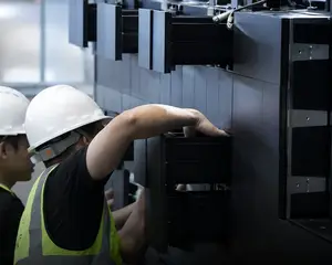
The SPKI-166 does not rely solely on visual effects to create the illusion of depth. Instead, it uses mechanical engineering to transform hundreds or thousands of LED modules into independently controlled “physical pixels” that can extend and retract along the Z-axis.
To understand how it works, we can break the system down layer by layer.
2. Layer 1: 165.6 × 165.6mm Modules and Independent Motion Mechanisms
The fundamental moving element of the SPKI-166 is the 165.6 × 165.6mm LED module.
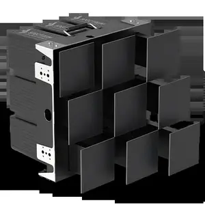
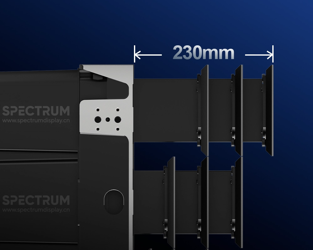
You can think of each module as a physical extension point on the kinetic LED surface. Within a standard 500 × 500mm quick-assembly cabinet, nine independent motion units are integrated in a 3 × 3 arrangement.
Why does “independent” matter?
If the entire cabinet could only move forward and backward as one piece, it would essentially function as a conventional sliding display.
The key difference is that each of the nine modules has its own independent motor and transmission mechanism.
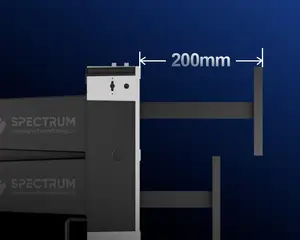
One module can extend to 230mm while another remains fully retracted, and others can stop at intermediate depths.
When hundreds or thousands of these independent height differences are combined across a large surface, the screen can create complex, continuously changing three-dimensional physical relief patterns.
3. Layer 2: High-Precision Linear Motion — How the Modules Move Smoothly and Stably
When an LED module extends forward, three mechanical problems immediately become critical: wobbling, misalignment, and jamming.
To keep each module moving in a straight line throughout its 0–230mm stroke, the SPKI-166 uses industrial-grade linear guides.
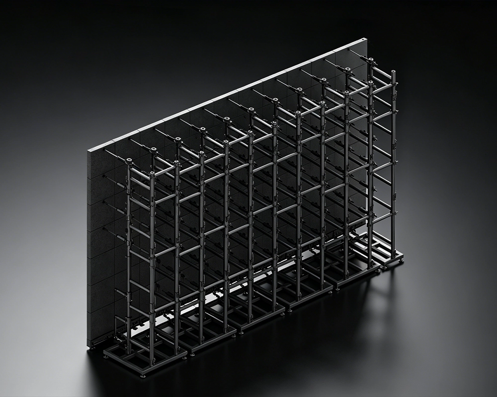
These guides work much like railway tracks, physically constraining the movement path of each module.
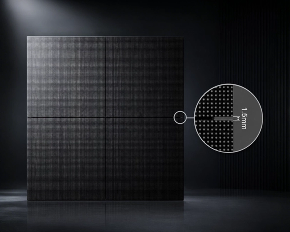
More than 90% of the mechanical components are precision-machined to minimize structural tolerances. The physical gap between modules is reduced to approximately 1mm, with a visual seam of approximately 0.2mm.
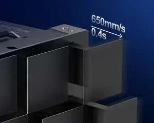
When the motor starts, the module moves smoothly along the linear guide and can reach speeds of up to 650mm/s.
But moving quickly is only half the challenge. The module also needs to stop accurately at its target position without excessive impact or deformation.
For this reason, the system combines precision mechanical buffering with motion-control algorithms to achieve smooth acceleration and controlled deceleration, allowing the modules to start smoothly and come to a soft, stable stop.
4. Layer 3: Industrial CAN Bus and Closed-Loop Servo Control — The “Neural Network” Behind Thousands of Motion Units
Controlling a few moving modules individually is relatively straightforward.
But what happens when a kinetic LED installation exceeds 100m² and contains thousands of independently moving modules?
This is where the communication architecture becomes critical.
Traditional solutions may rely on RS485 or other serial communication architectures, where large-scale systems can face challenges involving latency, signal interference, and data transmission reliability.
The SPKI-166 uses an industrial CAN Bus architecture.
CAN—Controller Area Network—was originally developed by Bosch for automotive electronic systems and is known for its strong resistance to electrical interference.
Inside the kinetic LED system, commands from the main controller are transmitted through the CAN Bus. The control board associated with each motion unit receives the relevant data and drives its corresponding motor.
But communication is only part of the system.
The other key technology is closed-loop servo control.
Conventional mechanical systems may use open-loop stepper motors. The controller sends a command, but without position feedback, it cannot directly verify whether the motor has actually reached the intended position. Under certain operating conditions, this can lead to missed steps or positional drift.
The SPKI-166 instead uses high-precision magnetic encoders for real-time position feedback.
If the controller commands a motor to move by a specified amount, the encoder continuously measures whether that movement has actually occurred. If a positional deviation is detected, the closed-loop system can immediately correct it.
This is what allows hundreds or thousands of modules across a large kinetic LED wall to move together with tightly synchronized positioning—almost like a precisely coordinated formation.
5. Layer 4: From Digital Signals to Physical Z-Axis Movement — The Complete Motion Process
Beyond its mechanical components, the SPKI-166 also needs a “brain” and a communication network.
The complete process can be understood in four stages:
1. Content Creation
A designer creates visual content in After Effects. The grayscale values within the control layer are extracted and translated into motion data.
2. Signal Transmission
The motion data is sent to the playback system. After processing, the commands are transmitted to the kinetic LED control system through the relevant network or DMX512 workflow.
3. Distribution and Execution
The CAN Bus distributes the motion commands to the corresponding cabinets and independent motion units.
4. Physical Z-Axis Movement
Based on the received displacement value—from 0 to 230mm—the servo system drives the high-precision linear mechanism, moving each 165.6mm LED module to its designated physical depth.
When dozens of frames of motion data are continuously transmitted every second, hundreds or thousands of modules constantly reposition themselves within the 0–230mm Z-axis range.
The result is a physical 3D relief surface that changes dynamically in real time.
▶Video · YouTubeTouch It. Watch It React. — the screen responds to the visitor in real timeWatch on YouTube →6. Conclusion: Four Integrated Layers Create a True Physical 3D Relief
The SPKI-166 does not move because of one motor or one piece of software. Its physical 3D effect is created through the coordination of multiple engineering systems.
Key Takeaways:
- Physical Motion Units: Independent 165.6 × 165.6mm LED modules form the basic moving elements, with nine motion units integrated into one lightweight 500 × 500mm cabinet.
- Mechanical Transmission: Industrial-grade linear guides and precision-machined components provide stable, smooth movement throughout the 230mm stroke.
- Communication and Feedback: Industrial CAN Bus communication works together with magnetic-encoder closed-loop control to coordinate up to 65,536 motion nodes while maintaining precise position feedback.
- Data-Driven Motion: Grayscale information is converted into physical Z-axis displacement, transforming digital content into real-world three-dimensional movement.
In other words, the SPKI-166 is not simply an LED screen with moving parts.
It is a mechatronic display system in which digital pixels and physical movement become part of the same visual medium.
For more information about the SPKI-166 or a customized 3D kinetic LED solution, contact the Spectrum Display team through the Spectrum Display official website.
7. Frequently Asked Questions (FAQ)
Q1: If the motor in one module fails, will it affect the movement of the entire cabinet?
A: No. The SPKI-166 uses an independent motion mechanism for each unit. If one module develops a fault, it will not mechanically lock the other modules, and the rest of the display can continue operating.
The system also supports both front and rear maintenance, allowing engineers to locate and replace an individual faulty unit efficiently.
Q2: How is the industrial CAN Bus wired inside the screen?
A: The system uses a serial bus topology in which multiple motion nodes are connected along the same bus.
This architecture significantly reduces the amount of internal cabling, lowers the risk of signal degradation caused by cable aging, and helps maintain a cleaner and more compact internal cabinet structure.
Q3: Does the 230mm extension stroke place stress on the internal cables?
A: The SPKI-166 uses protected cable-routing structures, including cable chains and concealed rotating cable-routing mechanisms.
As the modules repeatedly extend and retract, the cables remain protected within the routing system rather than being directly stretched by the high-frequency movement.
Q4: If power or the control signal is suddenly lost, will the modules fall or retract uncontrollably?
A: No. The internal guide and transmission mechanism incorporates a physical self-locking structure.
If power is lost, the modules remain at their current positions rather than suddenly dropping or moving uncontrollably.
Q5: Does the mechanical motion system require regular lubrication?
A: The industrial linear guides and transmission mechanisms receive long-life lubrication treatment before leaving the factory.
Under normal indoor operating conditions of 0–40°C, routine operation requires little additional lubrication. The primary environmental requirement is to keep the installation free from excessive dust, corrosive gases, and other contaminants that could affect the mechanical system.